Rj45 Pinout Diagram - Rs232 Rj45 Pinout - Molex rj45 connector, rj45 magjack breakout, transceiver board.. Rj45 cat5e cat6 wiring diagram. Molex rj45 connector, rj45 magjack breakout, transceiver board. Rj45 (registered jack 45) is the connector that consists of 8 metal connection point. Cat cables, usart modules, rs232 to ttl converters, rj45 modules. A pinout is a specific arrangement of wires that dictate how the connector is terminated.
Ether crossover cable wiring diagram rj45 colors and 👉 crossover cable wiring pinout and diagram a crossover cable also known as xover cable follows the t568a scheme at one end and t568b scheme at the other. This article explain how to wire cat 5 cat 6 ethernet pinout rj45 wiring diagram with cat 6 color code , networks have become one of the essence in computer world and for better internet facilities ti gets extremely important to built a good, secured and reliable network. A wiring diagram is a simplified traditional photographic depiction of an electrical circuit. Click to check the right one for you or print as reference. 8p8c modular connector plugs rj45 modular connector crimper rj45 for fixed wiring.
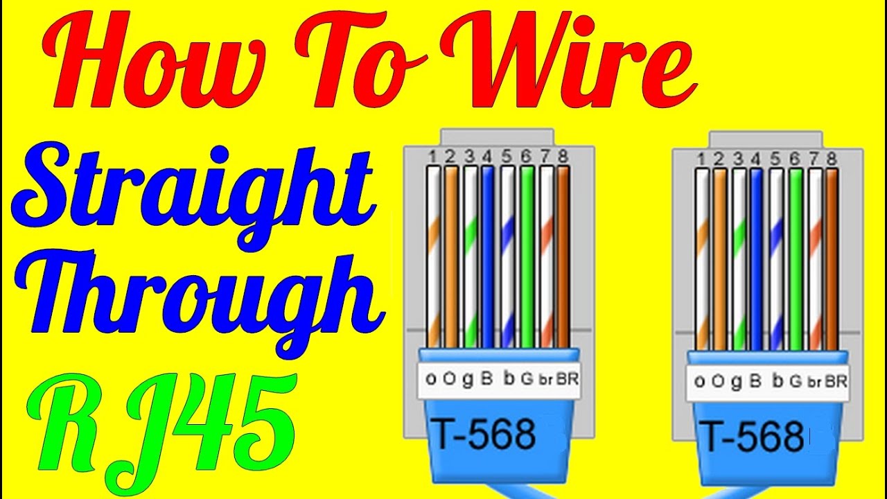
How To Make Straight Through Cable Rj45 Cat 5 5e 6 Wiring Diagram Youtube from i.ytimg.com In some network applications, the equipment is so close together that a crossover. Determine the serial pinout of your opengear device. Pinout of ethernet 10 / 100 / 1000 mbit (cat 5, cat 5e and cat 6) network cable wiringnowdays ethernet is a most common networking standard for lan (local area network) communication. This article explain how to wire cat 5 cat 6 ethernet pinout rj45 wiring diagram with cat 6 color code , networks have become one of the essence in computer world and for better internet facilities ti gets extremely important to built a good, secured and reliable network. 21 posts related to m12 to rj45 wiring diagram. A pinout is a specific arrangement of wires that dictate how the connector is terminated warning: Adapters required to connect to various types of ports, by pinout. 8p8c modular connector plugs rj45 modular connector crimper rj45 for fixed wiring.
Rj45 to bnc wiring diagram.
When ti comes to built your own reliable network most of the users don't know how to wire ethernet cables to built up a. Rj45 pinout diagram shows wiring for standard t568b t568a and crossover cable. The ethernet cable used to wire a rj45 connector of network interface card to a hub, switch or network outlet. Bt to rj45 wiring diagram. The following are the pinouts for the rj45 connectors so you can check which one you have or make up your. A pinout is a specific arrangement of wires that dictate how the connector is terminated warning: The wiring diagram is shown in table 1. A pinout is a specific arrangement of wires that dictate how the connector is terminated. Cat5 cabling diagram cat5 stripping and terminate ch 1 recommended cat55e rj45 cable assemblies for use with lantronix device servers. Cat cables, usart modules, rs232 to ttl converters, rj45 modules. Rj45 to bnc wiring diagram. Rj45 pinout diagram shows the way how that connector provides communication with network devices. 8p8c modular connector plugs rj45 modular connector crimper rj45 for fixed wiring.
Where to use rj45 connectors In some network applications, the equipment is so close together that a crossover. A rj45 connector is a modular 8 position 8 pin connector used for terminating cat5e or cat6 twisted pair cable. A pinout is a specific arrangement of wires that dictate how the connector is terminated. Db9 to rj45 wiring diagram.
1 from On cat5e wiring diagram wall plate. Cat 3126 ewd wiring diagrams.pdf. A rj45 connector is a modular 8 position, 8 pin connector used for terminating cat5e or cat6 twisted pair cable. On the left side is the hikvision camera's pigtail, on the right side is the rj45 connector. Rj45 wiring diagram a or b. Wiring scheme a (or t568a) used for rj45 wiring, utilises different wiring colours to scheme b (or t568b). 8p8c modular connector plugs rj45 modular connector crimper rj45 for fixed wiring. Cat cables, usart modules, rs232 to ttl converters, rj45 modules.
Rj45 colours and wiring guide tia / eia 568 a b author:
Pinout of ethernet 10 / 100 / 1000 mbit (cat 5, cat 5e and cat 6) network cable wiringnowdays ethernet is a most common networking standard for lan (local area network) communication. How to terminate cat5 cat5e cat6 cat6a cable. Rca to rj45 wiring diagram. Both schemes are perfectly normal to use providing they are not mixed. Rj45 pinout diagram shows wiring for standard t568b, t568a and crossover cable! This article explain how to wire cat 5 cat 6 ethernet pinout rj45 wiring diagram with cat 6 color code , networks have become one of the essence in computer world and for better internet facilities ti gets extremely important to built a good, secured and reliable network. Rj45 (registered jack 45) is the connector that consists of 8 metal connection point. Rj45 serial pinout options and diagrams. A pinout is a specific arrangement of wires that dictate how the connector is terminated. Rj45 wiring diagram t568a standard. Rj45 pinout diagram shows wiring for standard t568b t568a and crossover cable. Pinout 8 pin rj45 (8p8c) female connector at the hub. T1e1j1 schematron.org t1 cables use four wires:
T1/e1/j1 rj48 cable diagram the following illustration provides the wiring connections for straight or crossover cables. 21 posts related to m12 to rj45 wiring diagram. Rj45 pinout diagram shows the way how that connector provides communication with network devices. Wiring scheme a (or t568a) used for rj45 wiring, utilises different wiring colours to scheme b (or t568b). The following are the pinouts for the rj45 connectors so you can check which one you have or make up your.
Ip Camera Wiring Diagram Cornick from s3.amazonaws.com When ti comes to built your own reliable network most of the users don't know how to wire ethernet cables to built up a. Wiring scheme a (or t568a) used for rj45 wiring, utilises different wiring colours to scheme b (or t568b). Rj45 exists at the end of the ethernet cables that is used for internetwork communication. Rca to rj45 wiring diagram. Each part should be set and linked to different parts in specific manner. A wiring diagram is a simplified standard photographic representation of an electric circuit. Cat5 cabling diagram cat5 stripping and terminate ch 1 recommended cat55e rj45 cable assemblies for use with lantronix device servers. It was introduced commercially in 1989 and became ieee standard 802.3 in 1983.
Pinout 8 pin rj45 (8p8c) female connector at the hub.
Adapters required to connect to various types of ports, by pinout. Rj45 serial pinout options and diagrams. Rj45 cat5e cat6 wiring diagram. 21 posts related to m12 to rj45 wiring diagram. A rj45 connector is a modular 8 position, 8 pin connector used for terminating cat5e or cat6 twisted pair cable. T1e1j1 schematron.org t1 cables use four wires: 5 not used 6 rtn signal return common reference for logical signals. Compatible with all cat and udp cable. Both schemes are perfectly normal to use providing they are not mixed. A rj45 connector is a modular 8 position 8 pin connector used for terminating cat5e or cat6 twisted pair cable. 8 pin rj45 (8p8c) male connector at the cable. This article illustrates the serial pinouts of opengear rj45 serial ports, past and present. Pinout 8 pin rj45 (8p8c) female connector at the hub.